- Developed NCAP-compliant system level and functional level requirements & test scenarios for model verification
- Developed perception module; Implemented AMM Estimator to predict the Time to Collision (TTC); Designed FCW + AEB logic using State flow and integrated with AEB/FCW controller in Simulink
- Performed Unit testing creating test harnesses for modules using Simulink Test; Conducted MIL testing in Simulink & generated Embedded C++ code for SIL using Embedded Coder
- Requirements
- Driving Scenario Designer
- Sensor fusion for Multi-object tracking
- Autonomous Multi-modal predictor
- Forward Collision Warning + Automatic Emergency Braking Controller
- Vehicle Dynamics
- Preliminary Inferential Testing
- MIL and SIL
Requirements
- Get the stakeholder’s concern
- Warn the driver if there is a chance for collision with the vehicle ahead
- If required, brake the vehicle on behalf of the driver
- Use that to define the Task/item/ feature to be developed
- FCW – Forward collision warning to alert the driver of the potential collision with the vehicle ahead of the ego Vehicle in the form of visual, audible, and haptic warning
- AEB – Automatic emergency braking to provide brake assist to stop the vehicle and avoid the collision if the driver is not responding to the FCW or his brake effort is not good enough to avoid the collision
- Requirements domain
- Functional
- Safety
- Robustness – should pass the NCAP tests 7/9
- Quality – Deals mainly with comfort – sticking to friction ellipse while braking
- Challenges in managing Requirements,
- Gotta make sure the requirements are interpreted correctly and converted into the right specifications before implementation so that we don’t have to modify the C++ code again and again
- This can be done effectively using Requirements manager in Simulink, Creating a Test harness using Simulink Test
- A few requirements include,
- Functional
- Assertion violation
- Division zero
- Dead logic
- Functional
- Ego Vehicle following an accelerating Lead vehicle in the same lane for a Highway driving
- Functional, robust, safety – Another vehicle entering the lane – check if it avoids the collision applying brakes
- Lead vehicle decelerating in the same lane – same checks
CCRs – Car to car rear stationary – Lead vehicle stationary
CCRm – Car to Car rear moving – Lead vehicle moving but at a velocity lower compared to ego vehicle
CCRb – Car to Car rear braking – Lead vehicle currently moving at the same velocity as ego vehicle but decelerating
In all the above cases, it is expected of the vehicle to activate the FCW/AEB status at appropriate times as per the logic
Driving Scenario Designer
- It is an app used to design synthetic driving scenarios, configure sensors, and generate synthetic data for autonomous driving systems and algorithms
- Advantages
- Less expensive
- Saves time
- Multiple driving scenarios can be tested in a short span
- Much safer with no human involvement
- Steps
- Create roads, actors
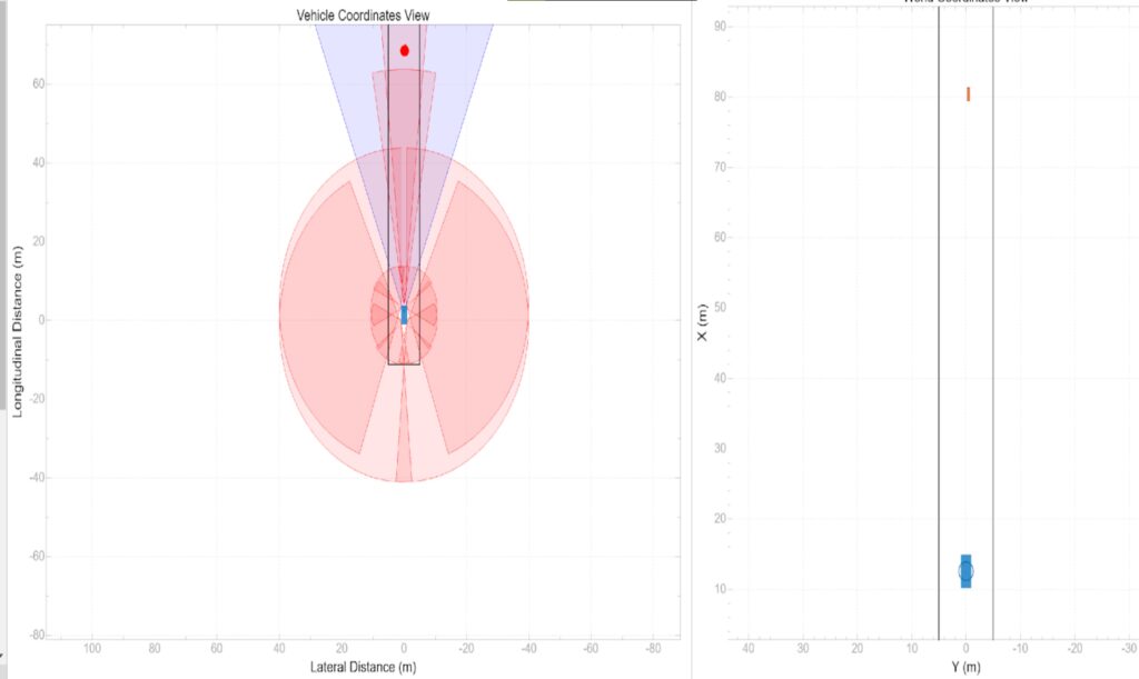
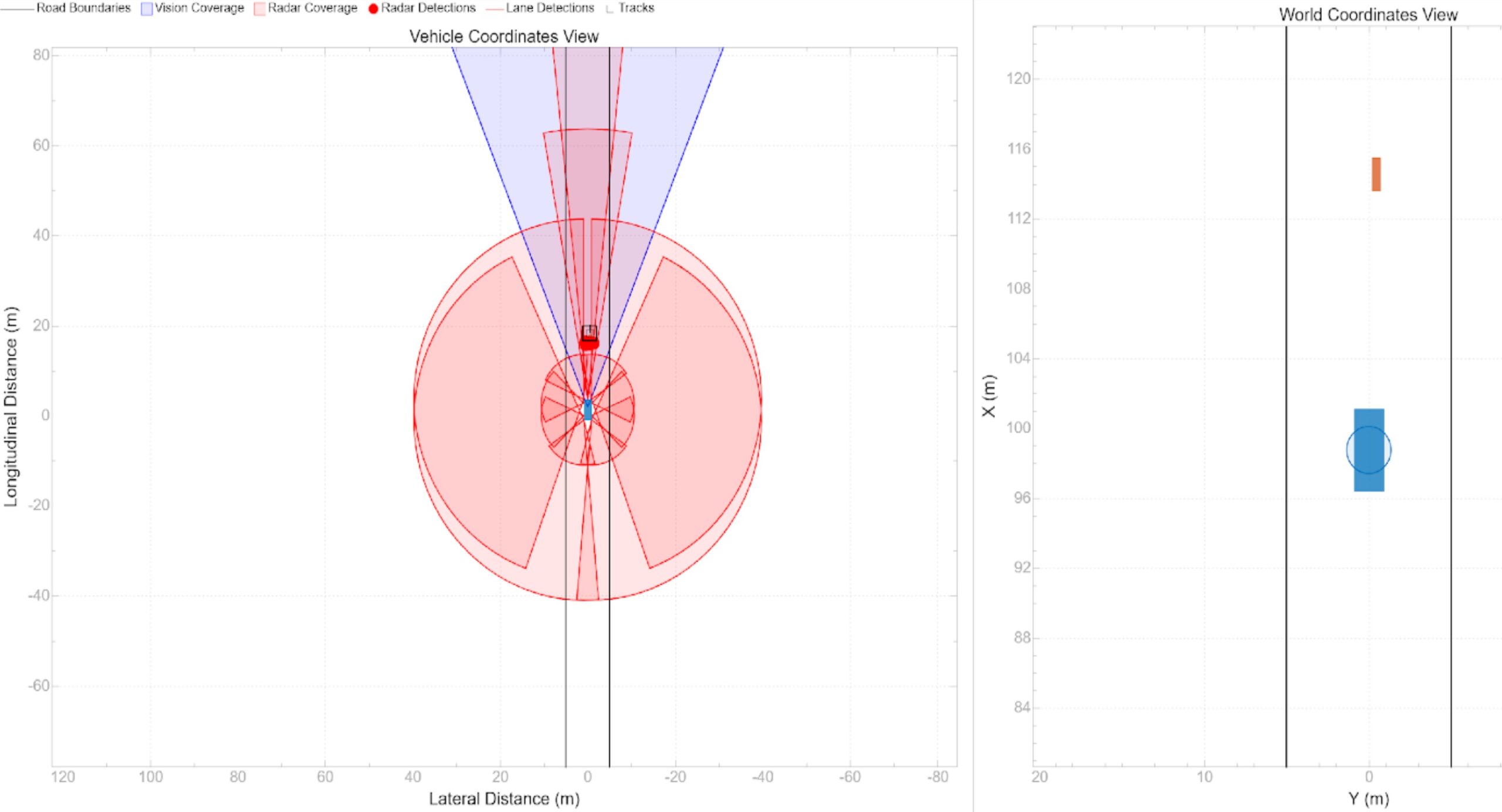
- Configure sensors after performing sensor coverage analysis
- 100m front radar and camera
- 5m sonars for parking
- 60 m radars
- We can load pre-built driving scenarios such as the EuroNCAP
- Export the scenario and sensor detections to MATLAB to generate a MATLAB script. Modifications can be made to the MATLAB code and can be imported into the app for simulation
Optimal sensor configuration involves,
- Choosing enough sensors to maximize coverage
- Improve object detection rate
- Sensors that complement each other to overcome individual shortcomings
Sensors usages
- Pedestrian detection, Road detection – Lidar, Camera, Infrared camera, Polarized camera
- Lane Detection – Cameras, Radar
- SLAM – Cameras and IMU
- Navigation – GNSS (GPS) and INS
- Ego positioning – Maps, Cameras, GPS, INS
EuroNCAP – Vehicle Under Test – 14 m/s and Bicyclist – 5.5 m/s after some time
One camera, 4 Radar, 8 Sonars
Sensor Fusion for Multi-object Tracking
- Detection Generator
- For generating the detections of the simulated actor poses
- Can specify the sensor placement
- Can set the sensor limitations
- We specify the actor profile
- Detection concatenation
- Detections from all the sensors/Radars (in this project) are concatenated and sent as a single bus to the Clustering block
- Detection clustering
- DBScan/GNN – To make sure multiple detections of the same object are not understood as different objects
- DBSCAN uses a radius threshold and all the detections within the threshold correspond to the detections of the same object
- Multi – Object Tracker
- To get tracks of the dynamic object detected at every time step
Autonomous Multi-modal Predictor
- Modes estimation
- 4 modes for target vehicles were considered
- Constant velocity same lane
- Left lane change
- Right lane change
- Constant acceleration same lane
- Used quintic polynomial (5th-degree polynomial) for finding the successive positions of each mode. Used known parameter constraints for finding the coefficients
- 4 modes for target vehicles were considered
- Finding the most probable mode
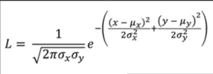
- Likelihood of each mode is found using the Gaussian distribution formula
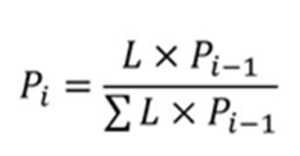
- The likelihood is used to find the probability of each mode
- Finding the TTC
- To find the TTC to the target vehicle considering its future path to be that of the most probable mode, we use circle based collision check
- The ego vehicle and target vehicle are approximated circles and the time at which the two circles intersect gives the TTC – The time at which the distance between the two is equal to the sum of their individual radii
FCW + AEB Controller
The main logic for AEB/FCW Controller,
- Velocity Controller – Use a PID controller to maintain a set speed – Cruise control
- FCW Stopping distance
- Use newton’s equations of motion to find the
- FCW stopping distance =0.5* RV_ego^2/ deceleration + Reaction time* RV_ego
- FCW stopping time = 1.5*RV_ego/deceleration
- Use newton’s equations of motion to find the
- PB1 stopping time – From Ego velocity and PB1 deceleration – 3m/sec^2 = V_ego/3
- PB2 stopping time – From Ego velocity and PB2 deceleration – 4m/sec^2 = V_ego/4
- FB stopping time – From Ego velocity and FB deceleration – 5m/sec^2 = V_ego/5
- State flow logic – Model and simulate decision logic using state machines
- There are 5 states
- Default
- FCW = 0, AEB = 0 and decel = 0
- FCW
- We enter the state when the following transition condition is met
- Relative distance <=FCW stopping distance
- FCW = 1, AEB = 0 and decel = 0
- PB1
- We enter the state when TTC <= PB1 stopping time
- FCW = 1, AEB = 1 and decel = PB1 decel
- PB2
- We enter the state when TTC <= PB2 stopping time
- FCW = 1, AEB = 2 and decel = PB2 decel
- FB
- We enter the state when TTC <= FB stopping time
- FCW = 1, AEB = 3 and decel = FB decel
- Whenever the vehicle comes to stop or the relative distance becomes greater than the FCW stopping distance, we go back to the Default state
- Accelerator
- If AEB status is 1, throttle commanded is 0
- Else, the same as the current acceleration
- Brake control
- Maximum driver input is given using a signal builder and the deceleration is commanded the AEB controller in State flow
Vehicle Dynamics
- The main objective is to find the ego vehicle’s state at the next time step
- Input – Throttle input, Brake input
- Output – ego vehicle’s next state
- Simple driveline and brake block – Uses two transfer functions that represent the trivial power train and braking. They convert the throttle input and brake input to the wheel forces
- Bicycle model
– These wheel forces are fed into the bicycle model that represents the vehicle’s dynamic
- Other vehicle parameters such as vehicle mass, yaw moment of inertia, and positions of COG can be given as input
- Rate transition block
- To make sure the frequency of state updates is the same as that of the sensor measurements
- Pack ego actor
- To make the ego vehicle’s state into a struct so that it can be fed back into the scenario reader to close the loop
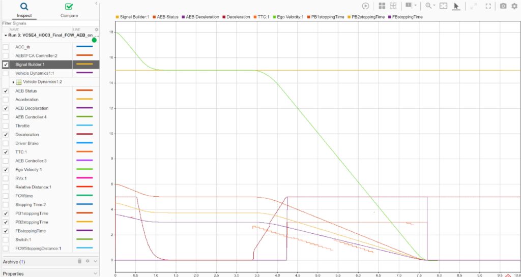
Preliminary Inferential Testing
- The integrated model is then subjected to preliminary testing
- We log the important signals
- FCW status
- AEB status
- Decel suggested AEB controller
- Driver braking input
- Driver set velocity
- RV
- RD
- FCW stopping time and distance
- PB1,2, and FB stopping time
- TTC
- Ego velocity and Acceleration in longitudinal direction
- Run the simulation opening the bird’s eye scope
- After the simulation ends, open the data inspector to analyze the signals
MIL and SIL
- Create a test harness for AEB
- Isolates this particular subsystem and tests the system in a synchronized test environment
- Using Simulink test, we can check if the system gives desired response
- We can go ahead and generate C++ code using the Embedded C++ coder
- It will have all the utility files, main cpp file, AEB.h, AEB.cpp, rtwtypes.h
- We can use Cmake to compile the code. Combine all the files and run